
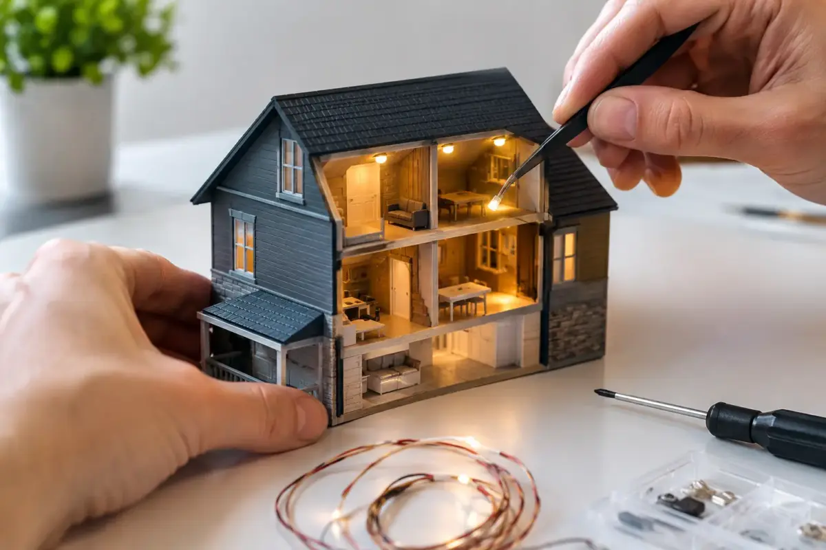
A lit cockpit, working navigation lamps or a warm glow behind the windows of a railway building can transform a finished model. Learning how to install model lighting is less about advanced electronics than careful planning: choosing the right LED, making room for wiring, and testing every stage before the fuselage or hull is closed for good.
The best time to decide on lighting is before assembly begins. Retrofitting is possible, particularly on buildings and dioramas, but it often means drilling around completed paintwork, forcing wires through awkward spaces and risking damage to delicate detail.
Plan the lighting before you build
Start by deciding what the light needs to achieve. On an aircraft, that may mean navigation lights, landing lights and a softly illuminated cockpit. A ship may need portholes, bridge windows and mast lights. Armour kits can benefit from headlamps or an interior glow, while a station, hangar or factory building may need general room lighting rather than individually lit fittings.
Study the kit parts and identify three practical things: where each LED will sit, where its wires will run, and where the power source will be hidden. Battery boxes suit display models that need no external control. A discreet socket is often better for larger dioramas or buildings, especially where several LEDs will be used. Railway modellers may instead want a supply compatible with their layout or DCC arrangement.
Scale matters. A 1:72 aircraft wingtip will not accommodate the same component as a 1:24 car headlamp. Fine enamelled copper wire, often called magnet wire, is useful where space is tight. For larger structures, ordinary stranded wire is easier to solder, more durable and simpler to trace if a fault develops later.
It is also worth considering whether a light should be visible at all. A bright, exposed LED can look like a modern torch inside a period vehicle or building. Most convincing lighting comes from controlling the source with clear parts, lenses, reflectors, fibre optics, light-blocking paint or a diffuser.
Choosing LEDs, resistors and power supplies
LEDs are the usual choice because they run cool, use little power and last far longer than traditional grain-of-wheat bulbs. Pre-wired LEDs are a sensible starting point for first projects, as their fine leads are already attached and many are supplied with resistors. Bare LEDs offer more flexibility, but require confident soldering and correct resistor selection.
For scale work, 0402 and 0603 surface-mount LEDs are exceptionally small and suit instrument panels, vehicle lamps and navigation lights. They are delicate, however, and their wires can be damaged by repeated bending. Three-millimetre and five-millimetre LEDs are easier to handle and work well in buildings, larger ships and display bases, although they may need sanding, shaping or recessing to avoid an oversized appearance.
Choose the colour with restraint. Warm white works well for older domestic, industrial and vehicle interiors. Cool white can suit more modern subjects, but can appear harsh if used unfiltered. Red and green are appropriate for port and starboard navigation lights, while amber is useful for warning lamps and certain vehicle lighting. Clear LEDs can be tinted with transparent colours where a specific lens shade is required.
Every conventional LED needs current limiting, normally provided by a resistor. Without one, the LED may fail almost immediately. The resistor value depends on the supply voltage, LED forward voltage and desired brightness. In practice, using a higher-value resistor is usually safer for models: it reduces brightness, heat and battery drain, and scale lighting rarely needs to be at full output.
For example, a white LED on a 9V supply might commonly use a resistor around 680 ohms to 1k ohm, depending on the LED and the brightness wanted. Check the manufacturer’s specification rather than relying on a single rule of thumb. If you are using a pre-wired LED, confirm its stated operating voltage before connecting power.
Use only low-voltage DC power supplies intended for hobby or electronic use. Never connect model lighting directly to mains electricity. A regulated supply avoids the fluctuations that can shorten LED life or alter brightness, and a switch on the display base makes the finished model far more practical to enjoy.
How to install model lighting neatly
Dry-fit the main parts before drilling or gluing anything. Mark wire routes with a pencil, then open shallow channels inside fuselage halves, hulls, walls or baseboards. A motor tool can speed this work, but hand tools offer more control around thin plastic. The aim is to let the wire sit below the joining surface, so it cannot hold two parts apart when the model is assembled.
Before fitting an LED, paint the inside of the surrounding part black. This blocks light from bleeding through thin plastic, especially on aircraft fuselages, ship hulls and building walls. Follow it with the interior colour where appropriate. Silver paint or foil can be used behind a lamp as a reflector, but it should not bridge bare electrical contacts.
Fix LEDs with a small amount of canopy glue, PVA or a compatible adhesive once their position is confirmed. Avoid flooding clear lenses with solvent cement or cyanoacrylate, as fumes can fog transparent parts. Heat-shrink tubing is excellent for insulating solder joints, though small pieces of Kapton tape or liquid electrical insulation can be more practical in confined spaces.
Keep positive and negative wiring consistent throughout the build. Red for positive and black for negative is conventional, but any system works if you label it clearly. Where multiple lights are fitted, connect them in parallel so each LED receives the intended voltage. A series circuit can be useful in some planned installations, but it is less forgiving: one failed connection can extinguish every light in that chain.
Solder quickly with a fine tip and clean flux, particularly around surface-mount LEDs. Too much heat can damage the component or melt insulation from the wire. If soldering feels like the obstacle, pre-wired LEDs and terminal blocks can produce a very tidy installation with less risk.
Test at every irreversible stage
Test the circuit before it goes into the model, again after the LEDs are fixed in place, and once more before each major seam is glued. A simple battery pack or adjustable low-voltage test lead is ideal for this. Check polarity first: LEDs are directional and will not light if connected backwards.
When testing, look beyond whether the LED works. Is the cockpit too bright? Does a navigation lamp shine through both sides of the wing? Can the wires be seen through a window? It is much easier to add black paint, a diffuser or another resistor before the model is closed.
Making the light look convincing
Brightness is the most common realism issue. Full-power LEDs may look impressive on the bench but overwhelming on a finished 1:35 vehicle or 1:48 aircraft. Adding resistance is usually the cleanest answer. A thin coat of clear paint over the LED, a small piece of frosted plastic or a painted light box can also soften the effect.
For aircraft instrument panels, light should illuminate dial faces rather than spill across the whole cockpit. For buildings, place LEDs above ceilings or behind partitions so the windows show pools of light rather than a visible point source. Fibre optics are particularly effective for tiny warning lights, star fields and distant lamps because the LED can remain hidden in a more accessible part of the model.
Consider access for maintenance as well. If a battery will eventually need replacing, build it into a removable base section or concealed roof. If the model will be transported, use a plug-and-socket connection between the subject and its base rather than permanently attaching fragile wiring.
Common faults and simple fixes
If nothing lights, first check the power supply, switch, polarity and every soldered joint. A single broken wire is more likely than several failed LEDs. If one LED is dimmer than the others, check that it has the correct resistor and that no joint is loose. If an LED flickers when the model is moved, a wire may be strained at the point where it enters the fuselage, building or base.
Light bleed calls for black paint on the interior and, where necessary, a second coat. If a clear part has become cloudy from adhesive fumes, replacement may be the only perfect fix, which is why dry-fitting and suitable glues matter so much. Leave enough slack in wires to position parts comfortably, but not so much that loose loops become trapped in view through a window or canopy.
A carefully lit model does not need dozens of effects. One well-placed lamp, a believable level of brightness and wiring that remains invisible will often add more atmosphere than a complicated circuit. Take the time to plan the installation alongside the kit, paints and finishing materials, and the lighting will feel like part of the model rather than an afterthought.
